Deep Foundations provide support to structural loads when competent soils or rock in shallow foundations are not feasible due to weak, compressible soils near ground surface. ABE is experienced in a variety of deep foundation methods and techniques to provide long-term and cost-effective solutions, such as:
Drilled Piers / Drilled Shafts / Caissons
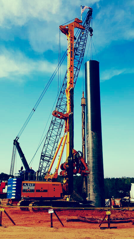
Drilled piers are for structures with high column loads. A drilled pier foundation is often an efficient and economical deep foundation choice. We have installed this foundation type with diameters ranging from 2 feet to 10 feet and depths ranging from less than 10 feet to in excess of 100 feet.
Cased Hole Method
A traditional method of constructing drilled piers consists of using temporary steel casing inserted into the drill hole. The casing is telescoped in decreasing diameters until a suitable bearing surface is reached. This method offers an opportunity for bearing surface inspection by a third party.
Slurry Hole Method
The slurry or wet construction techniques have gained traction in recent years as a faster, safer, more efficient, and more economical alternative to drilled pier construction. In this method, slurry (either polymer or bentonite) is pumped into the excavated hole as it is drilled. These holes are typically machine cleaned and the concrete is placed with a tremie pipe. The concrete displaces the slurry which is pumped out of the hole and either reused or discarded.
Segmental Casing Method
We offer Segmental Casing Method.
Rock Drilling
We offer Rock Drilling.
Micropiles
Micropiles, also known as minipiles, (and less commonly as pin piles, needle piles and root piles) are deep foundation elements constructed using high-strength, small-diameter steel casing and/or threaded bar.
Micropiles are small diameter (approx. 6 to 12 inches) deep foundations that are useful in a variety of applications.
Typically, they consist of a grouted column with some length of permanent steel casing and reinforcing bars. These foundation elements generally derive most of their capacity in skin friction. Because of the drilling equipment used for their installation, micropiles are easily embedded into rock.
Micropiles are also easily installed in low-headroom access situations and are often also used to retrofit old foundations or provide underpinning support when excavating in close proximity to existing structures.
Helical Micropiles
In certain situations, a helical micropile is useful in lieu of a grouted one. Helical piles are end-bearing steel elements that require no grout mix and are ready for use immediately upon installation (no curing time). These types of micropiles can be installed very quickly. However, they are generally limited in loading capacities and cannot be used in very soft or very hard subsurface materials.
Grouted Micropiles
Typically, they consist of a grouted column with some length of permanent steel casing and reinforcing bars. These foundation elements generally derive most of their capacity in skin friction. Because of the drilling equipment used for their installation, micropiles are easily embedded into rock.
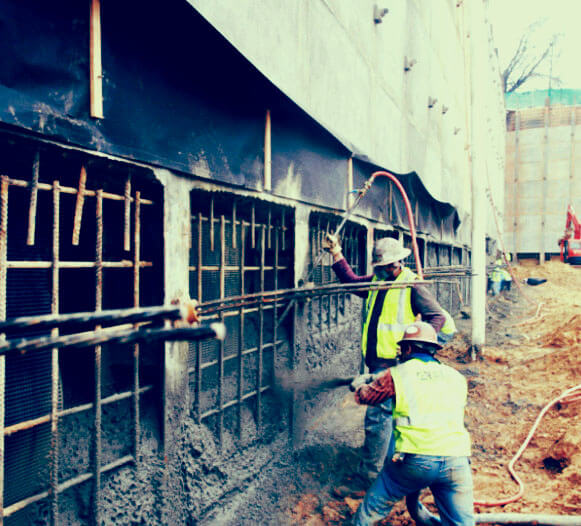
Rock Anchors
Rock Anchors generally consist of steel elements (bars or strands) grouted in a drilled hole. The bars or strands are subsequently tensioned. This provides lateral or vertical force to resist movement of a retaining structure. Anchors are often used for excavation support, or as a part of permanent retaining walls, or to resist up-lift forces on foundations. ABE Enterprises uses rock anchors to stabilize slopes and walls, provide tiebacks for bridges, stabilize dams, and secure caisson bottoms.
Mat Footing Uplift
When highly loaded structures bear on a shallow rock, a mat foundation is often used. These mat foundations also sometimes carry uplift requirements. Grouted anchors are drilled from the bearing surface into the rock and cast integral with the mat is an efficient solution to this problem.
Drilled Pier Uplift
The design of drilled piers sometimes requires rock anchors extending below the pier tip into bedrock for uplift capacity. This can be accomplished either during construction or after the construction of the drilled pier as a retrofit. These anchors are grouted with reinforcing steel. Grout to rock bond provides the required uplift capacity.
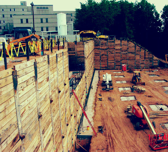
Underpinning
Underpinning is a solid foundation laid below ground level to support or strengthen a building.
Pit Underpinning
Traditional pit underpinning is often used when excavation must be made beneath a shallow foundation. This method of underpinning is most often utilized when a shallow foundation experiences unacceptable levels of settlement, or if an expansion or renovation of an existing structure requires excavation below the bearing surface of the existing foundation.
Typically, a pit is excavated directly beneath a portion of an existing footing to the depth of the new bearing surface. The pit is then filled with concrete and dry-packed. Once this process is repeated under the remaining portions of the footing, the underpinning is complete for that foundation.
Micropile Underpinning
If an existing foundation must have its bearing elevation lowered by a large amount, micropile underpinning may be more efficient than a deep, excavated pit. The advantage of this type of underpinning is that it may be accomplished prior to excavation and the versatility of the micropile allows for several load-transfer options.
Testing
ABE can perform a variety of tests on surfaces.
Compression Load Testing
Compression Load Testing
Tension Load Testing
Tension Load Testing
Lateral Load Testing
Lateral Load Testing
Statnamic Testing
Statnamic Test
Osterberg Load Cell Testing
The slurry hole method of drilled pier construction precludes the opportunity for bearing surface inspection. Therefore, some other form of subsurface load-transfer characterization is often required. One way of evaluating the subsurface is with Osterberg Load Cell Testing (O-cell Testing).
The O-cell test consists of a bi-directional expandable load cell that is placed near the bottom of a test shaft. Concrete is placed in the shaft and allowed to cure. Once the concrete is cured, a load test is run by inflating the cell at the bottom of the shaft. Since the cell expands upward and downward, the test allows for independent assessment of both the end bearing and skin friction capacity of the shaft. Once the load transfer is defined, the production shafts can be designed or re-designed, often with improvement upon original assumptions of geotechnical shaft capacity. ABE has performed multiple such tests throughout the Atlanta area and southeast and continues to offer this value engineering service on all drilled pier projects.